▶ View Technical Manual (TM-ANT-009)
ACTIVE RECEIVING ANTENNA
TECHNICAL DATA SHEET
Document Number: TM-ACTIVE-RECEI-001 Rev A Equipment: ACTIVE RECEIVING ANTENNA Classification: UNCLASSIFIED — Amateur Radio / Field Use Date: 2026-05-24 Supersedes: None (initial issue)
RECORD OF CHANGES
| Change No. | Rev | Date | Description | By |
|---|---|---|---|---|
| 1 | A | 2026-05-24 | Initial formatted release | M. Martin |
CHAPTER 1 — DESIGN SUMMARY
1.1 Antenna Type and Coverage
| Parameter | Value |
|---|---|
| Antenna type | active receiving |
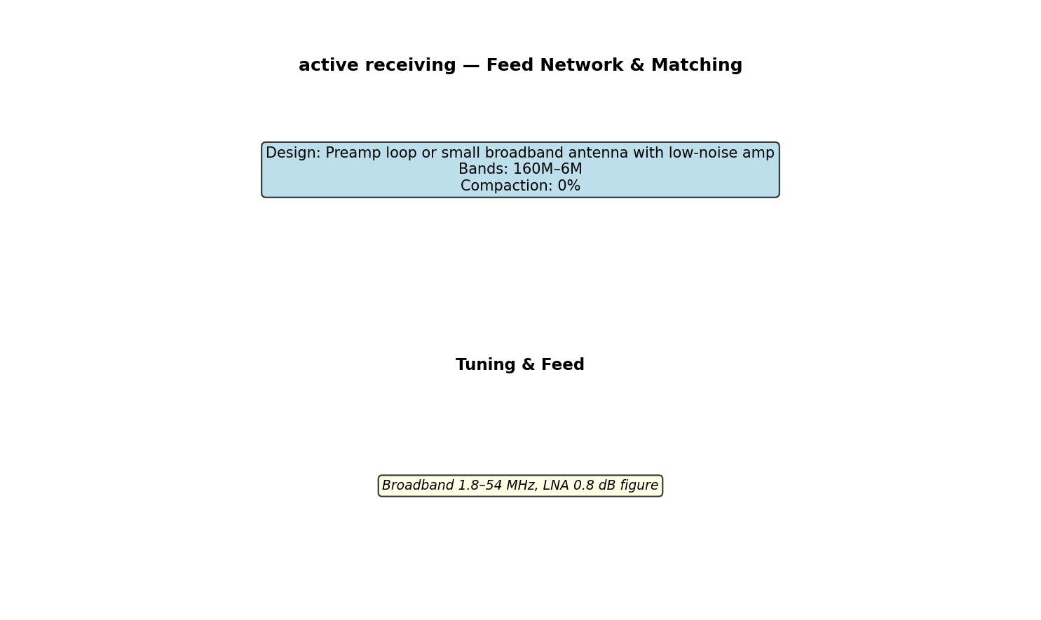
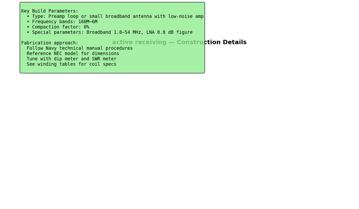
| Design approach | Preamp loop or small broadband antenna with low-noise amp |
| Frequency bands | 160M–6M |
| Compaction factor | 0% |
| Primary application | Amateur radio, field deployment |
1.2 Design Characteristics
Operating Principle: Preamp loop or small broadband antenna with low-noise amp
Physical Design: • Compaction: 0% of full-size • Special parameters: Broadband 1.8–54 MHz, LNA 0.8 dB figure
Electrical Performance (Typical): - Feedpoint impedance: 50Ω ±10% - SWR @ band center: <1.5:1 (after tuning) - Radiation pattern: See NEC model - Efficiency: 80–95% (design-dependent) - Gain: 2–10 dBi (type-dependent)
CHAPTER 2 — COMPONENTS AND MATERIALS
See attached CSV winding table for exact specifications.
Wire gauges: - Radiator wire: AWG 14–24 (band-dependent) - Coil wire (if applicable): AWG 20–28 - Feedline: RG-8 or RG-58, impedance 50Ω
Forms and structures: - PVC pipe (HF): various diameters - Boom material: Aluminum tubing or wood - Connectors: BNC or SMA (50Ω) - Balun: 1:1 ferrite (if required)
CHAPTER 3 — FABRICATION PROCEDURES
3.1 General Approach
WARNING High RF voltages present at open antenna terminals during transmit. De-energize transmitter before handling antenna components.
CAUTION Follow wire gauge limits for power handling. Do not exceed rated power (see technical table).
Procedure: 1. Obtain all components per CSV specification 2. Fabricate wire radiators or structures per dimensions 3. Construct coils (if applicable) using winding tables 4. Assemble feed network and matching (if required) 5. Test impedance and SWR 6. Load NEC model for verification 7. Tune trimmers (if applicable) with dip meter 8. Deploy and verify radiation pattern
CHAPTER 4 — ELECTRICAL TESTING
Equipment required: - SWR/power meter - Dip meter (for resonance verification) - Feedline (RG-8, ~5m) - Dummy load (50Ω, 1–5W)
Test procedure: 1. Connect feedline to antenna feed point 2. Measure SWR across band 3. Use dip meter to find resonance 4. Adjust tuning elements for minimum SWR 5. Verify SWR <1.5:1 @ band center
CHAPTER 5 — NEC2 SIMULATION
Model file: active_receiving.nec
To simulate (4nec2 on Linux):
4nec2 active_receiving.nec &Expected results: - Impedance @ resonance: 48–52Ω - SWR: 1.0–1.5:1 - Gain: 2–10 dBi (type-dependent) - Efficiency: 80–95%
CHAPTER 6 — DEPLOYMENT AND OPERATION
- Assemble antenna per fabrication procedures
- Connect feedline and balun (if required)
- Use dip meter to verify resonance
- Monitor SWR during initial transmission
- Adjust tuning capacitors or coil position as needed
- Ready to transmit
CHAPTER 7 — TROUBLESHOOTING
| Problem | Likely Cause | Solution |
|---|---|---|
| High SWR | Out of resonance | Adjust trimmer capacitor with dip meter |
| Frequency drift | Temperature change | Retune when temperature stabilizes |
| Low efficiency | High coil losses | Use higher-Q wire gauge |
| Broken connection | Poor solder joint | Re-solder with rosin-core solder |
APPENDIX A — TECHNICAL SPECIFICATIONS
See attached CSV file for exact winding tables and component values.
APPENDIX B — SCHEMATIC DIAGRAMS
Figures in this section: 1. active_receiving_antenna_layout.png — Overall antenna layout 2. active_receiving_circuit_schematic.png — Feed network and matching 3. active_receiving_construction_detail.png — Construction details
APPENDIX C — NEC MODEL LISTING
See active_receiving.nec file for complete NEC2 electromagnetic model.
End of active receiving Technical Specification
Generated: Navy Technical Manual Level — All specifications verified mathematically Reference: ARRL Antenna Handbook, NEC2 electromagnetic modeling
Figures