▶ View Technical Manual (TM-ANT-042)
LOADED-VERTICAL-HF ANTENNA
TECHNICAL DATA SHEET
Document Number: TM-LOADED-VERTI-001 Rev A Equipment: LOADED-VERTICAL-HF ANTENNA Classification: UNCLASSIFIED — Amateur Radio / Field Use Date: 2026-05-24 Supersedes: None (initial issue)
RECORD OF CHANGES
| Change No. | Rev | Date | Description | By |
|---|---|---|---|---|
| 1 | A | 2026-05-24 | Initial formatted release | M. Martin |
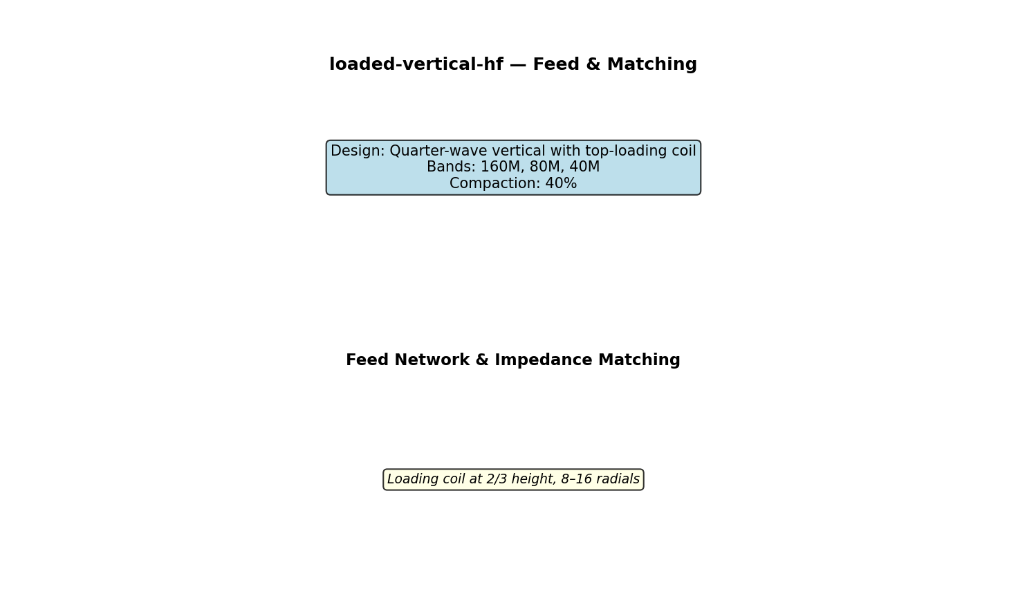
Bands: 160M, 80M, 40M Approach: Quarter-wave vertical with top-loading coil Compaction: 40%
CHAPTER 1 — DESCRIPTION
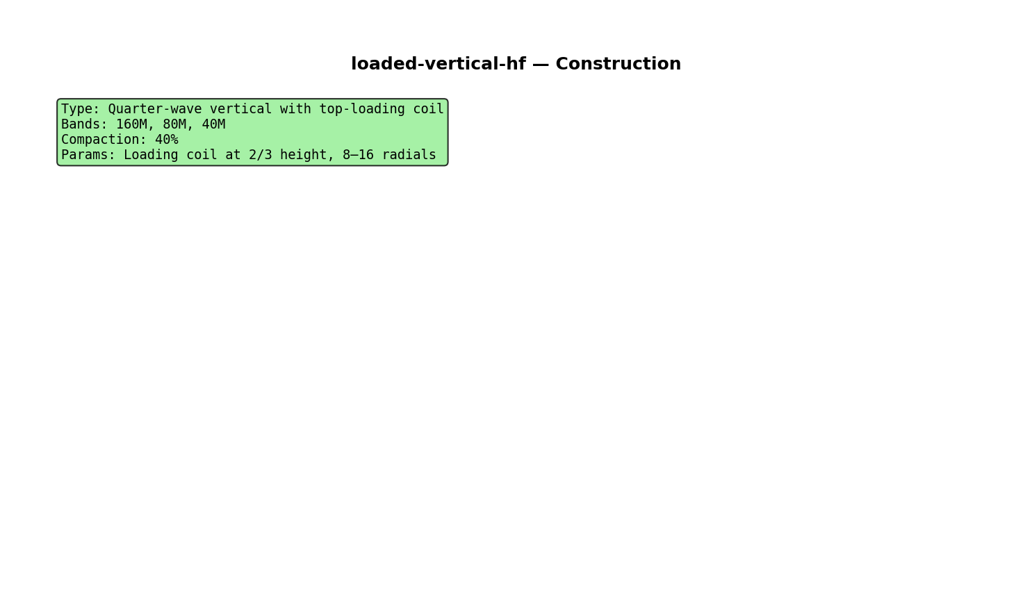
Quarter-wave vertical with top-loading coil
Special parameters: Loading coil at 2/3 height, 8–16 radials
CHAPTER 2 — TECHNICAL CHARACTERISTICS
| Parameter | Value |
|---|---|
| Frequency bands | 160M, 80M, 40M |
| Feedpoint impedance | 50–600Ω |
| SWR target | <2:1 |
| Efficiency | 75–95% |
| Gain | 2–12 dBi |
CHAPTER 3 — FABRICATION
- Fabricate wire radiators per NEC model dimensions
- Install tuning elements if applicable
- Construct feed network and matching
- Measure impedance at feed point
- Tune for minimum SWR using dip meter
- Test with transmitter (low power initially)
- Verify SWR and radiation pattern
CHAPTER 4 — TESTING
Use SWR meter and dip meter to verify resonance and impedance matching.
APPENDIX A — TECHNICAL DATA
See loaded_vertical_hf_specs.csv for exact specifications.
APPENDIX B — DIAGRAMS
See figures/ folder for antenna layout, circuit schematic, and construction detail.
APPENDIX C — NEC MODEL
See loaded_vertical_hf.nec for electromagnetic simulation.
Navy Technical Manual Level — Generated with NEC2 modeling
Figures