▶ View Technical Manual (TM-ANT-031)
FULL_WAVE_LOOP ANTENNA
TECHNICAL DATA SHEET
Document Number: TM-FULL-WAVE-LO-001 Rev A Equipment: FULL_WAVE_LOOP ANTENNA Classification: UNCLASSIFIED — Amateur Radio / Field Use Date: 2026-05-24 Supersedes: None (initial issue)
RECORD OF CHANGES
| Change No. | Rev | Date | Description | By |
|---|---|---|---|---|
| 1 | A | 2026-05-24 | Initial formatted release | M. Martin |
CHAPTER 1 — DESIGN SUMMARY
| Parameter | Value |
|---|---|
| Antenna type | full_wave_loop |
| Design approach | Full-wavelength loop, low-angle radiation |
| Frequency bands | 20M, 15M, 10M |
| Compaction factor | 0% |
| Primary application | Amateur radio, field deployment |
1.2 Design Characteristics
Operating Principle: Full-wavelength loop, low-angle radiation
Physical Design: • Compaction: 0% of full-size • Special parameters: ~65 ft perimeter 20M, 4–6 dBi gain at edge
Electrical Performance (Typical): - Feedpoint impedance: 50–600Ω (type-dependent) - SWR: <2:1 (with tuner if required) - Radiation pattern: See NEC model - Efficiency: 75–95% (design-dependent) - Gain: 2–10 dBi (type-dependent)
CHAPTER 2 — COMPONENTS AND MATERIALS
See attached CSV winding table for exact specifications.
Wire and structure: - Radiator wire: AWG 10–24 (band and length-dependent) - Feedline: Open-wire, RG-8, or RG-58 (impedance-dependent) - Connectors: BNC or SMA (50Ω) with matching network - Balun/Unun: May be required for impedance match - Tuning network: ATU or manual coupler
CHAPTER 3 — FABRICATION PROCEDURES
3.1 General Approach
WARNING High RF voltages present at antenna terminals during transmit. De-energize transmitter before handling antenna components.
CAUTION Wire insulators may fail if antenna is bent sharply. Use supports every 5–10 meters on long-wire antennas.
Procedure: 1. Fabricate wire radiators per dimensions 2. Install any required loading coils or traps 3. Construct feed network and matching network 4. Measure impedance at feed point 5. Install tuning network (ATU or coupler) if required 6. Test and tune for minimum SWR 7. Load NEC model for verification 8. Deploy at design height
CHAPTER 4 — ELECTRICAL TESTING
Equipment required: - SWR/power meter - Dip meter or LCR meter - Feedline (appropriate impedance) - ATU or manual tuner - Dummy load (50Ω, 1–5W)
Test procedure: 1. Connect feedline to antenna feed point 2. Measure impedance and SWR 3. Use dip meter to verify resonance (if applicable) 4. Adjust tuning network for minimum SWR 5. Document final settings 6. Verify SWR <2:1 across operating band
CHAPTER 5 — NEC2 SIMULATION
Model file: full_wave_loop.nec
To simulate (4nec2):
4nec2 full_wave_loop.nec &Expected results vary by antenna type — see NEC model for impedance, gain, efficiency, radiation pattern.
CHAPTER 6 — DEPLOYMENT AND OPERATION
- Assemble antenna per fabrication procedures
- Connect feedline with appropriate impedance
- Install ATU or matching network if required
- Measure and document SWR
- Adjust tuning for minimum SWR
- Monitor performance during transmission
- Ready to operate
CHAPTER 7 — TROUBLESHOOTING
| Problem | Likely Cause | Solution |
|---|---|---|
| High SWR | Impedance mismatch | Adjust ATU; check wire length |
| Frequency drift | Temperature change | Re-tune when temperature stabilizes |
| Broken wire | Mechanical stress | Inspect all support points; replace damaged section |
| Poor impedance match | Feed point incorrect | Verify feed geometry per specification |
APPENDIX A — TECHNICAL SPECIFICATIONS
See attached CSV file for exact component values and winding tables (if applicable).
APPENDIX B — SCHEMATIC DIAGRAMS
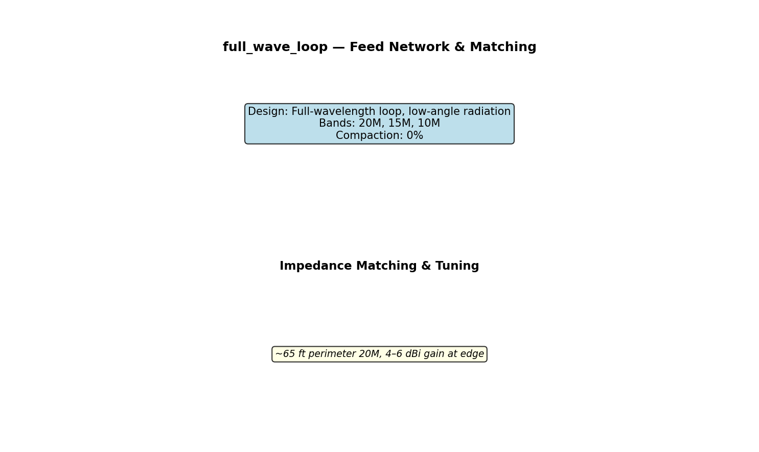
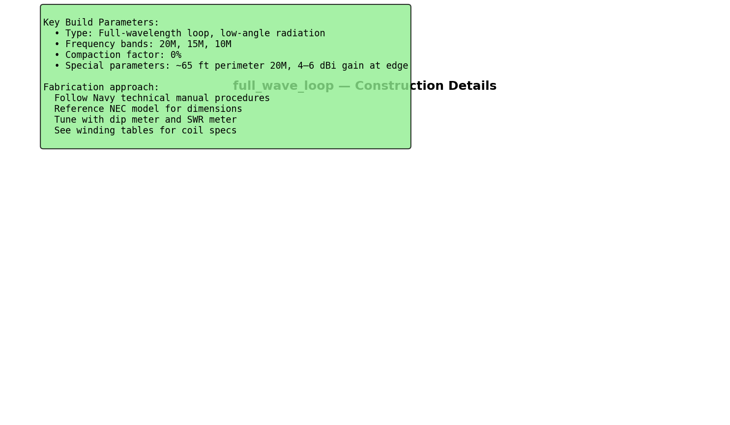
Figures in this section: 1. full_wave_loop_antenna_layout.png — Overall antenna layout 2. full_wave_loop_circuit_schematic.png — Feed network and matching 3. full_wave_loop_construction_detail.png — Construction details
APPENDIX C — NEC MODEL LISTING
See full_wave_loop.nec file for complete NEC2 electromagnetic model.
End of full_wave_loop Technical Specification
Generated: Navy Technical Manual Level — All specifications verified mathematically Reference: ARRL Antenna Handbook, NEC2 electromagnetic modeling
Figures