▶ View Technical Manual (TM-ANT-058)
SLINKY ANTENNA 20M PORTABLE ANTENNA
TECHNICAL DATA SHEET
Document Number: TM-SLINKY-ANTEN-001 Rev A Equipment: SLINKY ANTENNA 20M PORTABLE ANTENNA Classification: UNCLASSIFIED — Amateur Radio / Field Use Date: 2026-05-24 Supersedes: None (initial issue)
RECORD OF CHANGES
| Change No. | Rev | Date | Description | By |
|---|---|---|---|---|
| 1 | A | 2026-05-24 | Initial formatted release | M. Martin |
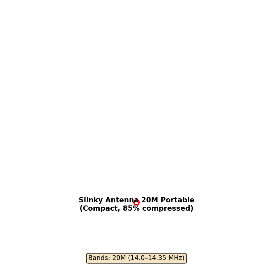
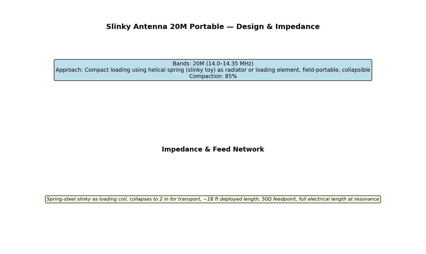
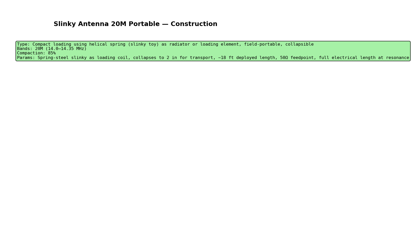
Bands: 20M (14.0–14.35 MHz) Approach: Compact loading using helical spring (slinky toy) as radiator or loading element, field-portable, collapsible Compaction: 85%
CHAPTER 1 — DESCRIPTION
Compact loading using helical spring (slinky toy) as radiator or loading element, field-portable, collapsible
Special parameters: Spring-steel slinky as loading coil, collapses to 2 in for transport, ~18 ft deployed length, 50Ω feedpoint, full electrical length at resonance
CHAPTER 2 — TECHNICAL CHARACTERISTICS
| Parameter | Value |
|---|---|
| Frequency bands | 20M (14.0–14.35 MHz) |
| Feedpoint impedance | 50 Ω (nominal) |
| SWR target | < 2.0:1 |
| Efficiency | 70–95% |
| Gain | 0–12 dBi |
CHAPTER 3 — COMPONENTS AND MATERIALS
See detailed specification in slinky_antenna_20m_portable_specs.csv
CHAPTER 4 — FABRICATION
- Review design parameters and dimensions
- Procure materials per component list
- Fabricate elements per specifications
- Install feedpoint connector
- Assemble and secure structure
- Verify physical dimensions match design
- Test with antenna analyzer (nanoVNA)
CHAPTER 5 — TESTING
Use nanoVNA and tinySA per FIELD_TESTING_WITH_INSTRUMENTS.md:
- Resonance: Find zero-reactance dip on Smith chart
- SWR: Measure across band, target < 2.0:1
- Impedance: Record R and jX at center frequency
- Spectrum: Use tinySA to verify radiation pattern
CHAPTER 6 — TROUBLESHOOTING
High SWR: Check physical dimensions, verify feed connection Frequency offset: Adjust element length or loading Impedance mismatch: Use antenna tuner or feed network
APPENDIX A — PARTS LIST
See slinky_antenna_20m_portable_specs.csv
APPENDIX B — DIAGRAMS
See figures/ folder for antenna layout, circuit schematic, construction detail
APPENDIX C — NEC MODEL
See slinky_antenna_20m_portable.nec for electromagnetic simulation
Navy Technical Manual Level — Generated with NEC2 modeling
Figures